CM-SD-40
The CM-SD-40 is a general purpose high density input VMEbus board, incorporating 16 Synchro/Resolver channels & features most demanded in first class military & industrial applications.

Input channels incorporate auto-conversion circuitry that fills a Dual port RAM with the latest conversion data. All I/O channels support most common S/R voltage ranges used in military and avionics equipment.
VMEbus S/D
Incorporating Built-In-Test that is based on wraparound loops that disconnect external S/R signals and connect internal test signals in order to verify correct module operation.

The metallic layer within the PCB benefits heat dissipation & uniform component temperatures, thus increasing component longevity & module MTBF. All versions are compatible at the function level, Industrial versions allow low cost software development.
Synchro-to-Digital
The CM-SD-40 offers a highly flexible I/O cabling solution using both the front panel & P2. Military versions with thermal overlay greatly improve capability to withstand shock & vibration.

Commercial

CM-SD-40/C
C: Commercial range >> Implements low cost Commercial plastic IC's rated for 0 to +70°C. Continuous board operation from 0 to +60°C. Class II industrial quality connectors. Storage from -10 to +85°C.
Industrial

CM-SD-40/I
I: Industrial range >> Manufactured with Industrial range plastic or ceramic IC's rated for -25 (-40) to +85°C. Continuous module operation from -20 to +75°C. Class II industrial quality connectors. Storage from -40 to +100°C.
Rugged+

CM-SD-40/R+/A
R+: Military Rugged+ range >> Implements ceramic IC's rated from -55 to +125°C. Class I MIL-C-55302 connectors. Conduction cooled PCB with thermal overlay. Operation from -40 to +85°C. Storage from -55 to +125°C.
Military 883

CM-SD-40/883/B
883: Military 883 range >> Manufactured with conduction cooled PCB & MIL-STD-883 B/C military ceramic parts (-55 to +125°C). Class I MIL-C-55302 connectors. Operation from -50 to +90°C. Storage from -55 to +125°C.
MIL-STD Components
- MIL-STD-810D Temperature (Methods 501.2 & 502.2)
- -55°C to +125°C ceramic military ICs
- Military Class V Printed Circuit Board
- MIL-C-55302 Class I Connectors
- MIL-STD-883 Analog & TTL chips
- MIL-E-5400 Class 1B (Temp. & Altitude)
- MIL-STD-810D Shock & Vibration (Methods 514 & 516)
- No PCB tracks in external layers
- MIL-STD-810D Saline Fog & Dust (Methods 507 & 509)
CM-SD-40 Specifications
- Input Channels: 16 SR/D channels, 16 bit resolution.
- R/D Converter: 4 x RDC-19220 with input multiplexer.
- Built-In-Test: A 12 bit D/R converter generates internal test signals. 100% coverage.
- Accuracy: 4 arc minutes ±1 LSB.
- Dual Port RAM: 4 KB of DPRAM, 16 bit wide.
- CM-SD-40/883/B MILITARY 883 VERSIONControl Register: Enable/disable VMEbus IRQs, select R/D converter resolution & set the module in BIT mode.
- VME Interrupter: I (3-7). Informs the VMEbus master at the end of a BIT cycle.
- Power Consumption: 3 Watts. +5VDC @ 275 mA, +12 VDC @ 7 mA, -12 VDC @ 67 mA.
- Weight: 550 gr. (I version), 640 gr. (R+ & 883 version).
- Synchro I/O: 3 wire standard per MIL-S-20708.
- Resolver I/O: 4 wire sine/cos per MIL-R-21530.
- Galvanic Isolation: >1000 Vp or 400 VDC.
- I/O Transformers: Scott-T pair per channel with 2 arc minutes angular accuracy.
- I/O Voltage Ranges: 11.8, 26 or 90 VRMS line-line. Input Ref.
- Voltage: 26 or 115 VRMS ±20%.
- Input Frequency: 400 Hz nominal ±40%.
- VMEbus Interface: A24/D16 Standard slave interface.
- VME Addressing: Two jumper blocks provide 256 mapping options.
- Mechanical Size: Single slot 6U (233.35x160 mm).
- Mechanical format:
- CM-SD-40/A: IEC-297 mechanics for 19 inch racks with I/O on front panel.
- CM-SD-40/B: Military IEEE P1101 wedgelock mechanics for ATR enclosures.
- Humidity: Up to 95% RH non-condensing.
- Altitude: Sea level up to 15 Km (50,000 ft.).
CM-SD-40 Features
- 16 bit resolution.
- High integration of I/O channels per board.
- Independent Synchro/Resolver voltage configuration per channel.
- Overvoltage/short-circuit protection on all channels.
- Full galvanic isolation on all I/O channels.
- 2 VA output power per channel.
- 4 KB Dual Port RAM for input conversion storage.
- Automatic input channel multiplexing, A/D sampling and data storage capability.
- Simple programming through the MCR.
- Built-In-Test wraparound circuitry allows testing of all S/R converters, analog and TTL chips.
- VMEbus Interrupter indicates end of BIT cycle.
- Operation under wide range of frequency & voltage options.
- Synchro/Resolver I/O signals via cannon connectors on front panel and VME64x connector on P2.
- P0 connector intended for key slot purposes.
- Commercial, Industrial, MIL-Rugged & MIL-STD-883 versions.
- Available in IEC-297 mechanics, I/O via front panel & military P1101.2 mechanics with wedge-locks.
- Conduction cooled PCB with thermal overlay in MIL-Rugged & 883 versions.
- Low power CMOS design.
- Extensive software support.
- Extremely simple programming.
- Excellent price/performance ratio.
- Two year guarantee.
-

Built-In-Test Diagram

CM-SD-40 Ordering
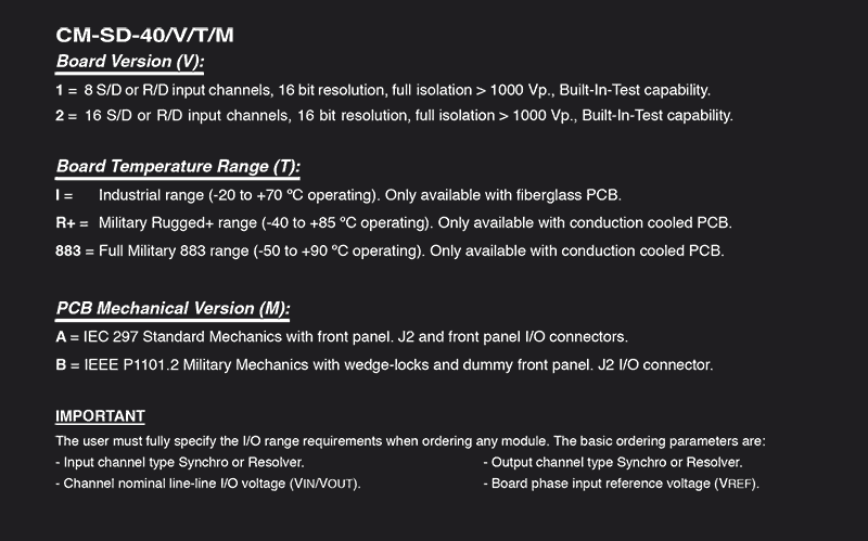
Ordering Example: CM-SD-40 /V /T /M
V (Board Version)
1: 8 S/D or R/D input channels, 16 bit resolution, full isolation >1000 Vp, Built-In-Test capability.
2: 16 S/D or R/D input channels, 16 bit resolution, full isolation >1000 Vp, Built-In-Test capability.
T (Board Temperature Range)
I: Industrial. Fiberglass PCB only.
R+: Military Rugged+. Conduction cooled PCB only.
883: Military 883. Conduction cooled PCB only.
M (PCB Mechanical Version)
A: IEC-297 Mechanics with front panel I/O connectors.
B: P1101.2 Military mechanics, dummy front panel & wedge-locks.
Ordering Example
Part Number Example: CM-SD-40/2/R+/B
- 16 S/D or R/D input channels, 16 bit resolution, full isolation >1000 Vp, Built-In-Test capability.
- Military Rugged+ range (-40 to +85°C operating).
- IEEE P1101.2 Military mechanics with wedge-locks.
Documentation
LEVEL 1, CM-SD-40 MAP: User´s manual. Module hardware functional description oriented toward software development.
LEVEL 2, CM-SD-40 MMT: Maintenance manual. Extended description intended for failure location in the module.
Software Support
Wind River Systems VxWorks Tornado: The CM-SD-40 is supported by VxWorks Tornado & is ideal for developing real time software under UNIX environments. A complete "C" language driver in source code is available at low cost. Drivers include a floppy-disk & user's manual.
Generic "C" Language Driver: A generic "C" language driver is also available in source code. The user may freely adapt for any application, operating system or ANSI "C" compiler. This code has been successfully compiled with the well established Mentor Graphics toolset.
* NOTE - Drivers for other leading operating systems can be optionally supplied under request.
* IMPORTANT - Fully specify I/O range requirements, parameters are: Input channel type Synchro or Resolver | Output channel type Synchro or Resolver | Channel nominal line-line I/O voltage (VIN/VOUT) | Board phase input reference voltage (VREF)