ATR Backplanes
-
COTS
VME64x
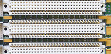
VMEbus backplanes permit intermixing of conduction-cooled IEEE-1101.2 modules or air-cooled IEC-297/IEEE.1101.1 modules. Fitted with Class I MIL-C-55302 VME64x connectors, J2 & J0 incorporate long pins for system I/O wiring with polarizing keys on J0 to protect against card insertion errors (VME64xK).
Read More -
COTS
cPCI | cPCI-S
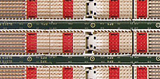
Compact PCI backplanes comply with IEC 1076 / PCI 1101.10/IEC 48D/118/CD standards & incorporate long pin P3/P4/P5 connectors. Specifications include; PICMG 2.0 R3.0 CompactPCI, Hot Swap PICMG 2.1 R2.0, Management Bus PICMG 2.9 & Keying PICMG 2.1 R1.0, PICMG CPCI-S.0 R2.0 2015 cPCI Serial.
Read More -
COTS
VPX | Open VPX
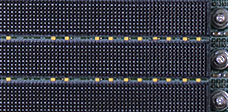
VPX backplanes are avaiable in VITA 46 / 65 / 66 / 67 in both 0.8” & 1" pitch size slot versions. Connectors J3 thru J6 are free for customer I/O wiring. J1 incorporates high-speed MultiGig mesh switched serial fabric connectors (up to 10+ GHz), full mesh topology, interconnects Rapid I/O, PCIe Gen 3 and 10 Gigabit Ethernet.
Read More -
COTS Hybrid
VPX-VME | cPCI-VME
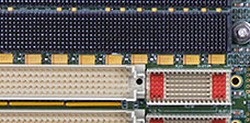
VPX-VME64x Hybrid Backplanes feature mesh-fabric slots that support both VITA46 (VPX) & legacy VME64x slots. cPCI-VME Hybrid backplanes support split combinations of slot arrays that are compatible with both standards. All VPX, VME & cPCI slots support Military IEEE-1101.2 wedge-lock mechanics.
Read More
Backplane Integration
CM ATR backplanes are available in 6U/3U; 5, 7 & 12 slot versions. Several custom Dual Redundant & Hybrid Backplanes are also available.
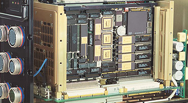
Backplanes have been designed to improve card-cage mechanical performance, incorporating active auxiliary electronics & additional options.
All chassis series incorporate True Military Monolithic Backplanes and Power Supply Units (PSU) that are custom made to match the enclosure mechanics.
Integrated backplanes are low noise, full military VMEbus, VPX or cPCI compatible and provide fully standard bus slot & signal daisy-chain functionalities.
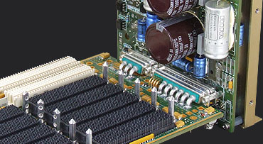
CM backplanes support one or two 100W power sockets for optional micro-size DC/DC military converters with user defined output voltage.
These converters are useful for increasing the +5VDC or +3.3VDC power lines or for generating isolated positive, negative or bipolar auxiliary DC voltages.
All connectors in the chassis are military standard components, allowing users to easily find the corresponding mating connector on the open market.
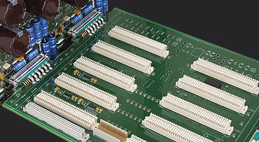
PCB screws distributed along machined channels in front/rear locations support & minimize PCB flexing during insertion, ejection, shock & vibration events.
Backplanes incorporate extra DC electrolytic capacitors for all PSU output voltages that complement high voltage input filtering.
Features
All CM backplanes interface the Power Fail Monitor, incorporating TTL logic circuitry for driving front panel LED indicators that are directly driven by the PSU.
Increased functions via the DC/DC redundant serial communication bus monitor; power on/off status, system board failure, correct input voltage range, bus data transfers, Temperature Supervisory Unit (TSU) with PSU shutdown & internal re-circulation fan speed control when over/under temperature.
Backplane PCB Power monitoring LEDs. Five green SMD LEDs indicate DC voltage on the TSU, +5VDC, +12VDC, -12VDC & +3.3VDC backplane power lines; three red SMD LEDs monitor when the PSU is driven to stand-by mode by the TSU.
Backplanes are supplied with military conformal coating per MIL-I-46058C in areas that do not affect connectors.
Class 1 military power connectors on PSU & Backplane offer shock & vibration reliability between chassis & internal modules, this allows high DC current rates with low voltage drops & minimum contact heating.
Integrated Reset Start Circuitry via a dedicated chip generates a 200ms pulse after power-up.
Final backplane slots in all chassis allows for bus functionality, containing power & control provisions to accept a Eurocard-size metallically caged Redundant PSU.
This single slot RPSU has the same capacity as the main PSU & both operate on a load-sharing basis to minimise component stress.
An optional TSU may be fitted for protecting card-cage electronics against extreme climate conditions, utilizing card-cage heaters & fan controls to limit the risk of high temperature failure.
Chassis Supervisory System (CSS)
The Chassis Supervisory System regulates chassis functions within all environments to prevent the chassis PSU overheating and aid in cold startups.
Boundaries can be easily established by the user to regulate and optimize the internal enclosure temperature.
TSU fitted units will drive an additional panel LED TEMP (over/under temperature) indicator that displays status in real time.
The TSU protects & aids in the longevity of our units by providing additional control of card-cage heaters for cold start-ups & fan speed during conditions of under and over trip point temperatures.
A delayed shut-down function to advise the CPU when power failure is imminent, allowing hard drives, relays & critical data to be shut down in an orderly manner.

Individual functions are optionally enabled or disabled by jumpers.
Remote control operation of the CSS allows the user to set the system to stand-by operation or disable the CSS. This can be utilized in situations where the ATR system is only required for a few hours but remains available on demand.
Typically, applications such as in battleships & submarines will require this feature. Note: stand-by power consumption is ≂40 Watts.
Disabling the CSS during an emergency can be carried out via a remote battle-switch to remove under/over temperature protection limits.
During battle situations it is crucial that the ATR system will remain available despite the risk of system over-stress.
Backplane 6U & 3U Lineup
-
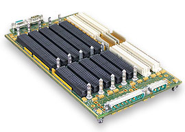
VPX-VME Hybrid: 7-Slot (6U - 0.8" Pitch)
-
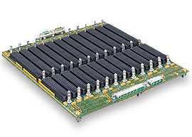
VPX: 12-Slot (6U - 0.8" Pitch)
-
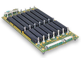
VPX: 7-Slot (6U - 0.8" Pitch)
-
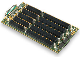
VPX: 7-Slot (6U - 1" Pitch)
-
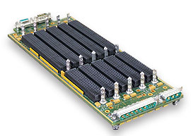
VPX: 5-Slot (6U - 0.8" Pitch)
-
VPX: 5-Slot (3U - 1" Pitch)
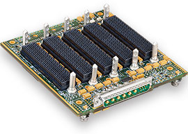
-
VPX: 6-Slot (3U - 0.85" Pitch)
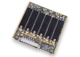
-
VME: 12-Slot (6U - 0.8" Pitch)
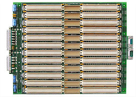
-
VME-cPCI Hybrid: 7-Slot (6U - 0.8" Pitch)
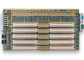
-
VME: 7-Slot (6U - 0.8" Pitch)
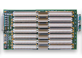
-
VME: 5-Slot (6U - 0.8" Pitch)
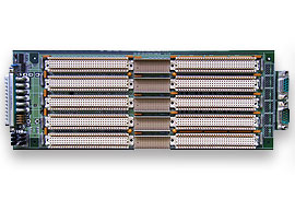
-
cPCI: 12-Slot (6U - 0.8" Pitch)
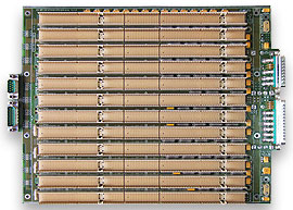
-
cPCI: 7-Slot (6U - 0.8" Pitch)
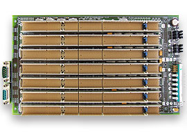
-
cPCI: 5-Slot (6U - 0.8" Pitch)
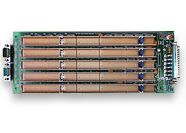
-
cPCI-S.0: 5-Slot (3U - 1" Pitch)
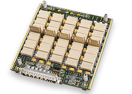
VME64x
- VME64x backplanes permit intermixing of conduction-cooled IEEE-1101.2 modules or air-cooled IEC-297/IEEE.1101.1 modules.
- CM VMEbus backplanes are designed with 12 layers and 2 dedicated ground shielding layers. MIL-C-55302 Class 1 VME64x connectors & MIL-STD-883 TTL components are fitted as standard.
- VME64x - Military VME64x backplane fitted with 5 row 160 pin J1/J2 and 95 pin J0 connectors.
- VME64xK - Military VME64xK backplane fitted with 5 row 160 pin J1/J2 & 75 pin key-slot J0 connectors have polarizing keys so that any given board fits only in its connector-coded slot, protecting against card insertion errors (ref: VME64xK).
- Bus Grant and IACK* Daisy-Chain jumpers are installed in compliance with VMEbus specifications.
- All backplane slots are backward compatible with standard VME32 boards having 3-row DIN connectors.
- CM VME backplanes incorporate specific TTL logic circuitry for driving up to 5 front panel LED indicators, ON, SYSF, ACF & VME. Units fitted with a TSU may also drive a panel LED TEMP indicator.
- All backplane J2 & J0 connectors incorporate long pins so all user free signals are available for I/O wiring.
- The last slot of our backplanes allows for bus functionality, but also contains power and control provisions to accept a eurocard-size metallically caged Redundant PSU.
- A single slot RPSU may have the same capacity as the main PSU & operate on a load-sharing basis to minimize component stress.
- CM backplanes allow straight forward I/O prototyping & hand-wire wrapping.
cPCI / cPCI-S / cPCI-VME Hybrid
- Compact PCI backplanes are designed by CM according to IEC 1076 / PCI 1101.10/IEC 48D/118/CD standards. Supported specifications include PICMG 2.0 R3.0 CompactPCI, Hot Swap PICMG 2.10 R2.0, System Management Bus PICMG 2.9 and Keying PICMG 2.10 R1.0. PICMG CPCI-S.0 R2.0 2015 CompactPCI Serial.
- CM cPCI backplanes are manufactured with 12 layers and 2 dedicated ground shielding layers.
- All cPCI Monolithic backplane slots are fitted with 7 row standard 2 mm P1/P2/P3/P4/P5 metric connectors.
- Military wedge-lock ANSI-VITA 30.1 conduction cooled modules may be arranged slot-by-slot or intermixed with IEC-61076-4-101 commercial & industrial fiberglass air cooled modules.
- cPCI-VME Hybrid backplanes support split combinations of slot arrays that are compatible with both standards.
- CM cPCI backplane can be factory fitted for +5VDC or +3.3VDC V(I/O) allowing 33Mhz or 66 MHz PCI clock distribution.
- PCI Interrupt Binding provides backplane assignments from System Slot 1. Interrupt signals INTA#, INTB#, INTC#, INTD# are assigned to logical board Slot 2, Slot 3, Slot 4, Slot 5, Slot 6 & Slot 7.
- cPCI backplanes incorporate long pin P3/P4/P5 connectors, allowing the user to connect or hand-wire all system I/O lines.
- All cPCI 6U slots are compatible with standard 3U cPCI modules having P1/P2 metric row connectors.
- The cPCI standard chassis backplane incorporates specific TTL logic circuitry for driving up to 5 front panel LED indicators. Units fitted with a TSU also drive a panel LED TEMP indicator.
- All cPCI backplanes incorporate a coin-type standby lithium battery. The 3VDC @ 7 mA/h battery is rechargeable from the standard chassis power supply.
VPX / OPEN VPX /VPX-VME Hybrid
- VPX backplanes, CM-BP-25/35/45/VPX & CM-BP-3U/VPX conform are available in VITA 46 / 65 / 66 / 67 in both 0.8” & 1" pitch size slot versions.
- J1 incorporates high-speed switched serial fabrics with performance up to 10+ GHz, interconnects Rapid I/O, PCIe Gen 3 & 10 Gigabit Ethernet.
- Full mesh topology supported for both 3U and 6U eurocard formats.
- CM VPX backplanes are 16-layer controlled signal impedance designed with two dedicated ground shielding layers. Connectors J3 thru J6 are free for customer I/O.
- CM VPX backplanes support MultiGig mesh Switched fabric connectors that provide significantly greater bandwidth capability with higher throughput and performance. Systems supported include, digital signal processing applications, FPGA and mass storage interconnects, etc.
- VPX-VME64x Hybrid backplanes feature mesh-fabric slots that support both VITA46 (VPX) & legacy VME64x slots. Hybrid backplanes support custom cross combinations of split VPX-VME64x compatibility for both standard & custom ranges.
- VPX backplanes integrate extra DC electrolytic capacitors for all Power Supply output voltages.
- All VPX backplanes incorporate a rear transition connector in position J3, J4, J5 & J6 with provision for J0, J2 & J3.
- All backplane slots support keying code pins connected to ATR chassis GND(Earth) & Military IEEE-1101.2 wedge-lock mechanics for VPX conduction-cooled modules.
- VPX backplanes integrate a Temperature Supervisory Unit (TSU) as standard.
MIL-STD Components
- MIL-STD-883 TTL Chips
- MIL-C-55302 Class I VMEbus Connectors
- MIL-C-24308 Class I Cannon Type D
- AISI 316 (A4) Stainless Steel Screws, Inserts & Accessories
- Military Class V Printed Circuit Boards
- MIL-I-46058C Multilayer Military Conformal Coating
- -55°C to +125°C Military Grade Passive Components & Power Semiconductors