6U S Description
Sealed, 0.8" pitch, low cost dry-air 6U chassis that incorporates air re-circulation fans inside. This minimum maintenance ATR is ideal for low wattage applications where ambient air is laden with hostile or harmful contaminants.
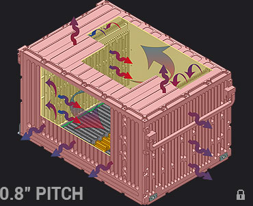
Heat generated within the enclosure is dissipated by a combination of cold-plate conduction, radiation and free-air convection through the chassis metalwork to the ambient environment. Internal air recirculation fans ensure constant airflow across modules.
CM-ATR-S5/S
The 6U S chassis is available in 5, 7, & 12 slot versions ( ½ ATR, ¾ ATR, 1 ATR), supporting VME, cPCI, VPX, VPX-VME & cPCI-VME hybrid backplanes. A total PSU power of up to 1050 watts may be installed. Custom modifications can be designed upon request.
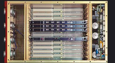
Internal layout is divided into 3 independent metallic partitions. I/O section at the front, card-cage in the middle & PSU section at the rear. This improves EMI/EMC performance & reduces PSU noise on system electronics.
Attention to I/O flexibility and easy board integration; allowing the intermixing of wedgelock IEEE P1101.2 conduction cooled boards, IEC-297 air cooled modules, Compact PCI 1101.1/IEC/118/ CD and VPX VITA 46.0/.1/.10/.3/.4/.7 air cooled boards.
6U S Performance
The 6U S chassis is suitable for low wattage sealed applications that demand moderate cooling capability.
S - Chassis Global Thermal Resistance (CGTR) coefficient:
ΔT/W = 0.26°C (½ ATR) | 0.23°C (¾ ATR) | 0.18°C (1 ATR) .
S - Chassis Payload Thermal Resistance (CPTR) coefficient:
ΔT/W = 0.316°C (½ ATR) | 0.279°C (¾ ATR) | 0.218°C (1 ATR).
For reliable operation it is recommended the maximum Payload Power not be exceeded. Subject to operating conditions.
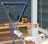
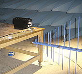
All CM 6U ATR chassis are delivered tested, qualified and certified per Military Standards MIL-STD-461E & MIL-STD-810F.
6U S Backplanes
CM 6U S military backplanes are available in VPX, VMEbus, cPCI, or combinations of VPX-VME64 or cPCI-VME64 hybrids, providing standard bus slot and signal daisy-chain functionalities. Designed to improve card-cage mechanical performance with 0.8 inch pitch slots & implement many features.
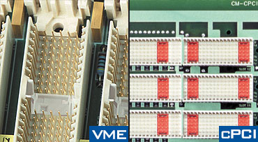
All 6U backplanes install specific TTL logic circuitry for driving up to 8 front panel user LED indicators. Units fitted with a Temperature Supervisory Unit will also drive an additional panel LED TEMP (over/under temperature indicator).
- VME64x backplanes conduction-cooled IEEE-1101.2 & air-cooled IEC-297/IEEE.1101.1 modules.
- Compact PCI backplanes according to IEC 1076 / PCI 1101.10/IEC 48D/118/CD standards.
- VPX backplanes conform to VITA 46.0/.1/.10/.3/.4/.7.
- VPX-VME64x Hybrid feature mesh-fabric slots that support both VITA46 (VPX) & legacy VME64x slots.
All S backplanes integrate a Temperature Supervisory Unit (TSU) with panel LED (over/under temperature) that controls Power Supply & Fan operation. Remote optoisolated control switches for ‘Battle-short’ & chassis PSU ‘on/standby’ are fitted as standard but not activated by default.
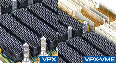
CM 6U military backplanes allow unlimited pin I/O wiring capability. Flexible top & bottom wiring integration is facilitated by a standard 25mm bottom cavity clearance to avoid requiring a custom backplane.
Final slots in 12 & 7 slot chassis allow for bus functionality & contain power/control provisions to accept a eurocard-size metallically caged Redundant PSU. A single slot RPSU up to 575W operates in parallel with main PSU on a load-sharing basis to minimize component stress.
Custom backplanes maybe designed upon customer request.
CM backplanes support one or two 100W power sockets for optional micro-size DC/DC military converters with user defined output voltage. The converters are useful for increasing the +5VDC or +3.3VDC power lines or for generating isolated positive, negative or bipolar auxiliary DC voltages.
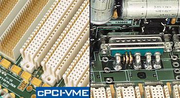
Class 1 military power input connectors offer reliable shock & vibration interconnectivity between chassis internal modules and allows high DC current rates with low voltage drops & minimum contact heating.
6U backplanes are supplied with military conformal coating. Printed circuits boards are partially coated per MIL-I-4658C in areas in which do no affect VPX, VME, cPCI, or I/O connectors.
All 6U models integrate similar backplane electronics for easy switch-overs, retrofits or replacement parts.
Read More
6U S Power Supplies
6U S chassis PSUs support a wide variety of AC/DC input voltages (MIL-STD-704 & MIL-STD-1275) and customer defined DC power output combinations up to 1050 Watts. Available in different versions to suit input voltage requirments.
CM-PS-25/S
All PSU models are fitted with Power Fail Monitor, remote voltage sensing, output voltage trim-up, time-delayed protection fuses, rear fan fuse and DC/DC converter remote shutdown.
To comply with MIL-STD-461E, a high capacity integrated EMI/EMC input voltage filter is fitted as standard on all 6U models. PSUs are custom made to match the enclosure mechanics.
200VAC 3-Phase PSU versions incorporate AC/DC rectifier stage prior to the VICOR FIAM front-end modules.
DC PSUs are equipped with a VICOR military Filter and Attenuator Module (FIAM). This front-end device is fitted prior to the DC/DC converters to provide EMI filtering, inrush current limiting and transient protection.
CM-ATR-35/S
Front-end FIAM modules are protected against DC reverse polarity. An optional reverse polarity diode may be fitted in series with power connector input pin IN (+).
Single-phase AC PSUs are fitted with a VICOR military Filter and Autoranging Rectifier Module (FARM) to provided EMI filtering, autoranging line rectification and inrush current limiting to meet MIL-STD-461E category A1b specifications for Electromagnetic Compatibility.
6U S PSUs incorporate isolated DC/DC converters & oversized hold-up capacitors to ensure proper operation during short power line failures. Outputs are protected against short-circuit, thermal-shutdown etc.
CM-ATR-45/S
The PSU
in S models is attached to the chassis rear panel, providing thermal conduction to the chassis frame.
Internal air recirculation dissipates heat generated via convection cooling that inturn is conducted through all chassis panels.
6U ATR S Specifications
CM-ATR-25/S |
CM-ATR-35/S |
CM-ATR-45/S |
|
| WIDTH | 130 mm | 170 mm | 271 mm |
| HEIGHT | 236 mm | 236 mm | 236 mm |
| DEPTH | 390 mm | 390 mm | 390 mm |
| WEIGHT | 5.2 Kg | 6.6 Kg | 10 Kg |
| CGTR COEFF | ΔT/W = 0.26°C | ΔT/W = 0.23°C | ΔT/W = 0.18°C |
| CPTR COEFF | ΔT/W = 0.316°C | ΔT/W = 0.279°C | ΔT/W = 0.218°C |
| SLOTS | 5 | 7 | 12 |
| PSU MAX POWER | 575 Watts (28 VDC 475 Watts) | 650 Watts (28 VDC 550 Watts) | 1050 Watts (28 VDC 950 Watts) |
| PSU V-INPUT | 28 VDC ±30%, 48 VDC ±30%, 72 VDC ±30%, 270 VDC ±30%, Autorange 90-132 VAC RMS & 180-264 VAC RMS 47-880 Hz, 3-Phase 200 VAC ±30% 47-880 Hz | ||
| STD BACKPLANE | 6U (0.8" Pitch), VME64X or cPCI or VPX or Hybrid VME64X/VPX or VME64X/cPCI | ||
| BOARD FORMAT | CCS: Conduction-cooled slots only or MCS: Slot-by-slot user configured card-cage allows intermixing conduction-cooled ANSI-VITA 48.2 & air-cooled ANSI-VITA 48.1 boards | ||
| INTERNAL FAN | 27 CFM | 54 CFM | 108 CFM |
| FRONT PANEL AREA | 101 mm x 172.5 mm | 141.5 mm x 172.5 mm | 243 mm x 172.5 mm |
| I/O SUPPORTED | 6 Power Pins (23 Amp) & 365 I/O Pins (5 Amp) | 6 Power Pins (23 Amp) & 822 I/O Pins (5 Amp) | 6 Power Pins (23 Amp) & 1057 I/O Pins (5 Amp) |
| OPERATING TEMP | -40 °C to +85 °C Operating Temperature, -55 °C to 100 °C Storage Temperature | ||
| MTBF | 25° GB 98,000 Hours, 65° AIC 32,000 Hours | 25° GB 86,000 Hours, 65° AIC 28,000 Hours | 25° GB 78,000 Hours, 65° AIC 24,000 Hours |
| MOUNTING TRAY | CM-TR-25/S | CM-TR-35/S | CM-TR-45/S |
6U COTS MODELS
These highly optimized 6U chassis incorporate all proprietary technologies, features and well established mechanical & electrical solutions developed during the past 27 years.
FAC:Flow-through airflow open enclosure.S:Standard sealed contaminant-free enclosure.
SEF:Sealed with Extended Fins contaminant-free enclosure.
SEF-HP:Sealed with Extended Fins + 18/20 Heat Pipes contaminant-free enclosure.
HES:Sealed fitted with 4 integrated heat exchangers contaminant-free enclosure.
HES-1Sealed 1" pitch, fitted with 4 integrated heat exchangers contaminant-free enclosure.
SIXHEX:Sealed fitted with 6 integrated heat exchangers contaminant-free enclosure.
SIXHEX-1:Sealed 1" pitch, fitted with 6 integrated heat exchangers contaminant-free enclosure .
SIXHEX-16HP:Sealed fitted with 6 integrated heat exchangers & 16 heat pipes contaminant-free enclosure.
SIXHEX-20HP-1:Sealed 1" pitch, fitted with 6 integrated heat exchangers & 20 heat-pipes contaminant-free enclosure.
SEVENHEX-CHP-1:Sealed 1" pitch, fitted with 7 integrated heat exchangers & 32, 36 or 46 heat-pipes contaminant-free enclosure.
6U ATR MIL Certificates
6U ATR S Ordering Information
CM-ATR-S5 /CT /B /I /W /3.3 /D1 /D2 /R /S /FP /TC /BC /CS /C
/S5 Enclosure Size- CM-ATR-25: ½ ATR - 5 Slots (0.8" Pitch).
- CM-ATR-35: ¾ ATR - 7 Slots (0.8" Pitch).
- CM-ATR-45: 1 ATR - 12 Slots (0.8" Pitch).
- S: Standard (0.8" Pitch) Sealed enclosure.
- VME64x: Military VME64x Backplane with 5 row 160 pin J1/J2 and 95 pin J0 connectors.
- VME64xK: Military VME64x Backplane with 5 row 160 pin J1/J2 & 75 pin key-slot J0 connectors.
- cPCI: Military Compact PCI Backplane.
- VPX: Military VITA 46 VPX Backplane.
- VPX/VME64x: Hybrid VPX mixed with VME64x Military Backplane.
- cPCI/VME64x: Hybrid cPCI mixed with VME64x Military Backplane.
- 28VDC: 28 VDC Input.
- 48VDC: 48 VDC Input.
- 72VDC: 72 VDC Input.
- 270VDC: 270 VDC Input.
- 90-264VAC: Autorange 90-264 VAC @ 47-880Hz Input.
- 200VAC-3Ph: 200 VAC 3 Phase @ 47-880Hz Input.
CM-ATR-25 - 5 Slot
- 300W: 28 VDC (+5 VDC @20A, +3.3 VDC @5A, ±12 VDC @8A).
- 400W: All PSUs (+5 VDC @20A, +3.3 VDC @5A, ±12 VDC @12A).
- A-475W: 28 VDC (+5 VDC @40A, +3.3 VDC @22A, ±12 VDC @8A).
- A-575W: All PSUs (+5 VDC @40A, +3.3 VDC @22A, ±12 VDC @12A).
- B-450W: 28 VDC (+5 VDC @20A, +3.3 VDC @45A, ±12 VDC @8A).
- B-550W: All PSUs (+5 VDC @20A, +3.3 VDC @45A, ±12 VDC @12A).
- C-475W: 28 VDC (+5 VDC @20A, +3.3 VDC @22A, +12 VDC @16A, -12 VDC @8A).
- C-575W: All PSUs (+5 VDC @20A, +3.3 VDC @22A, +12 VDC @21A, -12 VDC @12A).
CM-ATR-35 - 7 Slot
- 400W: 28 VDC (+5 VDC @40A, +3.3 VDC @5A, ±12 VDC @8A).
- 500W: All PSUs (+5 VDC @40A, +3.3 VDC @5A, ±12 VDC @12A).
- C-575W: 28 VDC (+5 VDC @20A, +3.3 VDC @22A, +12 VDC @25A, -12 VDC @8A).
- C-625W: All PSUs (+5 VDC @20A, +3.3 VDC @22A, +12 VDC @25A, -12 VDC @12A).
- D-550W: 28 VDC (+5 VDC @40A, +3.3 VDC @45A, ±12 VDC @8A).
- D-650W: All PSUs (+5 VDC @40A, +3.3 VDC @45A, ±12 VDC @12A).
CM-ATR-45 - 12 Slot
- 950W: 28 VDC (+5 VDC @80A, +3.3 VDC @45A, ±12 VDC @16A).
- 1050W: All PSUs (+5 VDC @80A, +3.3 VDC @45A, ±12 VDC @21A).
28 VDC = 28 VDC input only
- 3.3-75W*: 3.3VDC @ 22A (in Lieu of 3.3 VDC @ 5A), Optional DC/DC AUX0 converter on Backplane fitted for 3.3VDC
- NOTE: Option suited for 1st generation PSU models 300W/400W/500W. Note: If /3.3-75W is not selected, DC/DC power socket AUX0 remains free to the user
- D1: 100W Optional DC/DC Converter on Backplane. User defined output. Auxiliary DC/DC output options: +2VDC 50W, -2VDC 50W, +3.3VDC 75W, -3.3VDC 75W, +5VDC 100W, -5VDC 100W, +12VDC 100W, -12VDC 100W, +15VDC 100W, -15VDC 100W, +28VDC 100W, -28VDC 100W, +48VDC 100W, -48VDC 100W.
- Ordering Examples: 48-100W » 48VDC @ 2A | -5-100W » -5VDC @ 20A | 2-50W » 2VDC @ 25A.
- D2: Optional user defined output DC/DC converter on backplane.
CM-ATR- 35 & CM-ATR-45 only
- RA-475W: 28 VDC (+5 VDC @40A, +3.3 VDC @22A, ±12 VDC @8A).
- RA-575W: All PSUs (+5 VDC @40A, +3.3 VDC @22A, ±12 VDC @12A).
- TSU: Temperature Supervisory Unit.
- CMP: Standard CM front panel fitted with MIL-C-38999 connectors.
- UDP: User defined front panel layout (requires customer drawing).
- STC: Standard Top Cover. ‡ 20mm.
- HTC: High-profile Top Cover. ‡ 35mm.
- FTC: Low Profile Top Cover with cooling fins. ‡ 20mm.
- SBC: Standard Bottom Cover. ‡ below backplane 25mm.
- HBC: High-profile Bottom Cover. ‡ below backplane 50mm.
- MCS: Mixed Card-cage Slots (conduction-cooled & air-cooled boards).
- CCS: Conducton-cooled Card-cage slots (conduction-cooled boards only).
- B: Black, G: Navy Grey, E: Army Dark Earth, W: White, R: Red, PT: Platinum, YW: Yellow, GN: Green, BLU: Dark Blue, CR: Chromate MIL-C-5541 or O: Other (user defined).
CM-ATR-35/S/cPCI/28VDC/400W/3.3-75W/UDP/HTC/HBC/MCS/G
- 3/4 ATR, 7 slot, 6U VMEbus Avionics Enclosure.
- Sealed Enclosure.
- Extended 7 slot cPCI Backplane for 6U boards fitted with I/O on P3, P4 and P5 connectors.
- 28VDC input Power Supply Unit with 400W (+5VDC @40A, +3.3VDC @ 5A, ±12VDC @ 8A).
- (+) 3.3VDC @ 22A DC/DC converter on Backplane.
- User defined Front Panel layout.
- Extended high profile top cover.
- Extended high profile bottom cover.
- Universal, mixed card-cage slots.
- Enclosure Navy Grey color.
