ATR IO Wiring Systems & Solutions
-
COTS
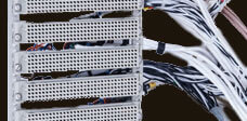
Mating I/O
Mating connectors are the industry standard approach to interconnect I/O signals lines with the bus architecture.
Read More -
CUSTOM COTS
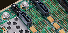
PCB Connectors
Integrated Backplane connector solutions that provide optimized connectivity for specific application I/O requirements.
Read More -
COTS / CUSTOM COTS
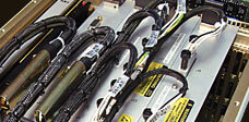
I/O Routing
CM standard and customized Top & Bottom I/O routing guides to distribute and support critical signals (RF & optical).
Read More -
CUSTOM COTS
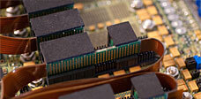
Flex Solutions
A custom I/O solution for compact systems with high density I/O and series production requirements.
Read More
Our chassis are designed with extra space in the front panel, top card-cage, and bottom Backplane areas to greatly reduce common I/O cabling issues.
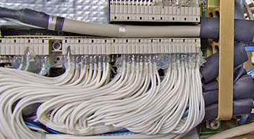
The use of rear mating modules/connectors to interface the bottom side VPX, VME or cPCI connectors is well established and provides a fast method for connecting to bus signals.
Wiring I/O signal lines using a harness module block to interconnect the system, integrators may choose an array of slot mating connectors (that are mechanically attached) and fit discrete I/O wires on connector contacts.
Alternatively, a custom PCB with soldered slot mating connectors can interface front panel connectors using circuit track signals and intermediate I/O connectors.
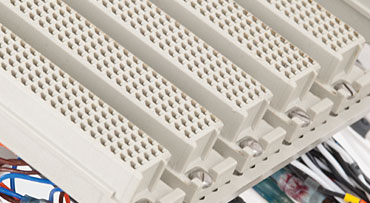
The advantages of this method is that the I/O block contains all mating connectors at once (single block harness), with no possibility of slot/pin shift or confusion.
The I/O block interface method provides improved mechanical reliability and strength when matched against slot-by-slot equivalents. It also provides better EMI immunity in PCB solutions shielded with ground layers.
Mating module practices ensure the Backplane and harness are two independent modules and is recommended for moderate signal density and medium production runs.
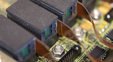
In high density signal systems such as VPX, the complexity of wiring hundred of I/O signals to a mating modules is a tiresome task as lines are difficult to place, measure and test.
Considerable mating forces may be required due to the high number of pins being inserted at once, and in 3U systems the issue of space becomes more prevalent. CM has developed solutions that can mitigate against these limitations, Read More
During a custom Backplane design process, customers may wish to resolve much of the I/O wiring process via the installation of connectors mounted directly on the Backplane PCB.
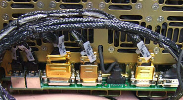
Payload I/O signals are routed through the Backplane PCB to a set of intermediate connectors (typically installed outside the card-cage) or beneath the Backplane.
PCB connectors pass I/O signals to chassis front panel by means of a complementary cabling solution (discrete wiring, cable wiring, flexible/rigid circuits, etc.).
In most cases, this solution allows for off-the-shelf connectors and cables to be used, prefabricated relatively inexpensively and with logical familiarity for any integrator.
A distinct advantage is the reduction in overall wiring height and interface that would otherwise utilize rear Backplane connectors via mating parts.
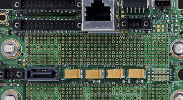
This solution provides greater control over the distribution of high speed signal connections and other less critical transmissions to reduce cross-talk and match impedance conditions.
Signal integrity losses observed in mating-transition connectors can be avoided to deliver greater performance in high speed VPX applications.
Independent cabling harnesses can be tailored for their signal integrity and EMC properties, following best practices to ensure optimum system performance and maintainability.
The selection of the most appropriate wiring techniques is a critical decision based on several factors (chassis space, signal density, connector type, cable bend radius, etc.).
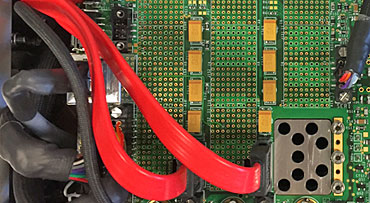
Contrary to mating connectors, custom I/O Backplane connectors fitted to the PCB must be defined during the design process. However, system revisions are expensive, hard to modify & repair.
The complete undertaking requires careful engineering (complex), with pin-out maps and signal definitions fully defined in the early stages of development.
For high speed applications (+20Gbps) this solution will deliver greater performance as it minimizes signal losses between interconnects. Note: Each application must be studied for viability.
Conduction & air-cooled payload cards may include a set of panel connectors that users wish to break-out to the ATR front panel.
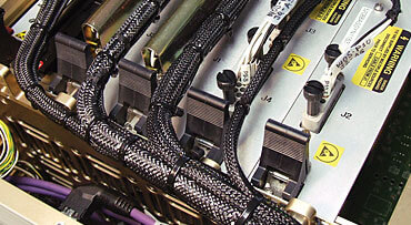
CM ATRs that are fitted with 'MCS' - Universal Card-cage Slots (mixed Conduction-cooled & Air-cooled Boards) support I/O wiring via general purpose Top and Bottom wiring plates.
CM can provide custom wiring plates, bosses and routing guides in order to support the distribution of critical application signal lines.
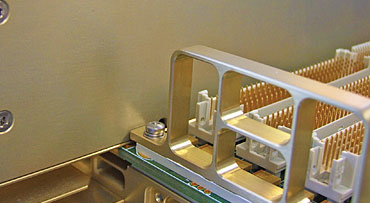
Radio Frequency, Fiber, and other specialist interconnects often impose routing constraints that must be observed from the payload front panel to the ATR Front Panel application connector.
Systems interconnects maybe incorporated across the patch panel to allow the easy removal of the ATR front panel assembly.
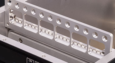
These 'multi-stage' engineered systems ensure all lines to the payload remain fixed and in place when the ATR Front Panel requires removal.
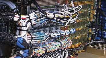
Wiring plates are provided as standard in this configuration for straightforward cable guiding, organization, clamping and I/O installation.
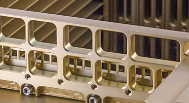
Custom designed wiring plates and patch panels (dock) allow integrators to easily route their payload panel front IO via the top cover cavity within the ATR and wire to the ATR front panel.
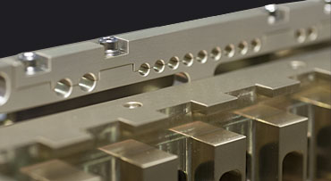
Intermediate patch panel connectors can be disengaged during servicing, keeping the critical IO routing to payload intact and untouched.
CM Computer offers customers a complete custom I/O wiring harness solution for our ATR range based on the latest Rigid-Flex circuit technologies. Read More
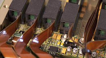
Flex and Rigid-Flex circuits are capable of carrying hundreds of signals within a small space, constituting an advanced wiring solution for high density I/O CM ATR enclosures.
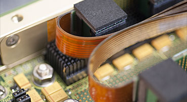
This cutting edge solution allow for auxiliary filters and components to be integrated in-line, providing greater freedom of signal density and packaging geometry.
In large productions CM flex circuits ensure repeatability and deliver significant system integration cost savings with no reduction in performance.
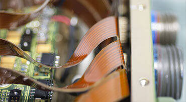
Track routing is predetermined and human wiring errors are eliminated. Integration of the latest VPX modules with high density I/O requirements can be easily integrated.
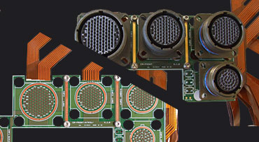
This hi-tech method is a vast improvement over conventional I/O wiring techniques and does not require modification to the Backplane PCB.
The complete ATR system I/O wiring is developed from Backplane pin-outs to the application Front Panel connector pins, combining all intermediary IO wiring steps.
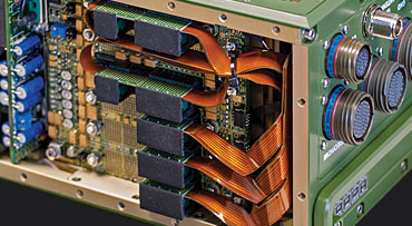
CM help customers define the optimum I/O configuration that meets their requirements. A comprehensive I/O wiring manual and set of engineering schematics are provided to our customers.
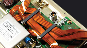
ATR systems with the Rigid-Flex solution are delivered from CM 'turn-key', fully tested and application ready for immediate deployment. Read More
Advantages
- High track density (up to 500 I/O signals in 3U systems).
- Does not require custom Backplane I/O signal routing.
- Shaped to fit where other solutions cannot.
- Provides superior signal integrity and electrical performance.
- Built-in signal track ground shielding.
- Greater standardization and repeatability.
- Greatly reduced installation time and cost.
- Signal impedance & cross-talk are consistent batch-to-batch.
- Occupies minimum space and volume.
- Minimizes I/O harness weight.
- Customized to provide optimum trace characteristics.
- Superior reliability with respect to conventional techniques.
- Not prone to human signal wiring errors.
- Straight forward disassembly from the Backplane.
- Allows easy ATR front panel removal and maintenance.
- Reduced internal chassis airflow restriction.
- High tech professional approach.
Disadvantages
- Requires careful design engineering and planning.
- Requires detailed chassis and Backplane electrical knowledge.
- Initial development time and cost.
- Hard to modify/repair once established (due to rigidity of printed circuits, no signal changes or system upgrades are possible).
- May be susceptible to damage if not properly handled.
- Only suitable for low and medium power signals.
Design Steps
- Customer must define to CM Computer chassis Front Panel.
- Customer must provide CM Computer with chassis I/O wiring harness drawings (VPX slot-to-panel pin-out assignment).
- CM computer provides customer with a 3D modeled solution.
- CM Computer provides customer with Flex and Rigid-Flex complete I/O harness solution (production units).
- Optionally, CM Computer can provide custom designed hardware tools for Flex and Rigid-Flex circuit automatic testing.