CM-AD-45
The CM-AD-45 is a general purpose 32 channel A/D (Analog to Digital) board that incorporates features most demanded in first class military and industrial applications.

On-board auto-conversion circuitry performs all tasks relative to multiplexing, sampling & converting of analog input signals.
Dual port RAM acts as a transparent communications device between the A/D converter and the VMEbus.
Analog to Digital
Extensive Built-In-Test per channel is based on a wraparound loop that disconnects external analog input signals and connects internal test signals in order to verify correct module operation.

The metallic layer within the PCB benefits heat dissipation & uniform component temperatures, thus increasing component longevity & module MTBF.
VMEbus A/D Converter
CM-AD-45 offers a flexible I/O cabling solution using connectors on the front panel & P2. Military versions with thermal overlay greatly improve capability to withstand shock & vibration.

All versions are compatible at the function level, Industrial versions allow low cost software development.
Commercial

CM-AD-45/C/A
C: Commercial range >> Implements low cost Commercial plastic IC's rated for 0 to +70°C. Continuous board operation from 0 to +60°C. Class II industrial quality connectors. Storage from -10 to +85°C.
Industrial

CM-AD-45/I/A
I: Industrial range >> Manufactured with Industrial range plastic or ceramic IC's rated for -25 (-40) to +85°C. Continuous module operation from -20 to +75°C. Class II industrial quality connectors. Storage from -40 to +100°C.
Rugged+

CM-AD-45/R+/A
R+: Military Rugged+ range >> Implements ceramic IC's rated from -55 to +125°C. Class I MIL-C-55302 connectors. Conduction cooled PCB with thermal overlay. Operation from -40 to +85°C. Storage from -55 to +125°C.
Military 883

CM-AD-45/883/B
883: Military 883 range >> Manufactured with conduction cooled PCB & MIL-STD-883 B/C military ceramic parts (-55 to +125°C). Class I MIL-C-55302 connectors. Operation from -50 to +90°C. Storage from -55 to +125°C.
MIL-STD Components
- MIL-STD-810D Temperature (Methods 501.2 & 502.2)
- -55°C to +125°C ceramic military ICs
- MIL-STD-883 Analog & TTL chips
- High stability MIL-STD-883 SRAMs
- Military Class V Printed Circuit Board
- MIL-C-55302 Class I Connectors
- MIL-R-39016 Relays (V.883)
- MIL-E-5400 Class 1B (Temp. & Altitude)
- MIL-STD-810 Shock & Vibration (Methods 514 & 516)
- No PCB tracks in external layers
- MIL-STD-810D Saline Fog & Dust (Methods 507 & 509)
CM-AD-45 Specifications
- Input channels: 32 independent single-ended channels or 16 independent differential channels.
- A/D converter: 12 bit industry standard Analog Devices A/D 1674. On chip Sample & Hold.
- Sampling speed: Programmable sampling speeds: 12.5, 25, 50 and 100 Ksps.
- DC Unipolar range: 0-5V, 0-10V, 0-50V, 0-100V.
- DC Bipolar range: ±2.5V, ±5V, ±10V, ±25V, ±50V, ±100V.
- AC ranges: 0-5V, 0-10V, 0-50V, 0-100V.
- Ranges in mA DC: 0-50 mA (0-20 mA, 4-20 mA).
- Input attenuators: A 10:1 voltage attenuator is available in board version /2. It must be connected to operate with input ranges above 10 V.
- Input protection: All analog inputs are protected against external over voltages up to 120 VDC.
- Dual port RAM: 4 KB of dual port SRAM, 16bits wide. The on board multiplexing/conversion circuitry fills data buffers in RAM with 16/32 or 2048 word size.
- Sampling cycles: All channels are converted & stored in RAM, freeing the master CPU.
- Control Register: Defines the RAM storage buffer size, enables/disables VMEbus interrupts, programs the A/D sampling rate and activates & Built-In-Test circuitry.
- Built-In-Test: BIT is based on two voltage references & dedicated relays distributed as to allow testing all on board analog & TTL devices.
- Accuracy: 0.05% for non attenuated input ranges. 0.2% for attenuated input ranges.
- Signal bandwidth: DC to 50 KHz.
- Input impedance: 470 K? default. Up to 5M? optional.
- VMEbus access time: 300 nsec. per RAM word transfer.
- VMEbus Interrupter: I(2-7). Indicates SRAM buffer filled with last converted data.
- VMEbus Interface: A24/D16 Standard slave interface.
- VME Addressing: Two jumper blocks provide 256 mapping options in the A24 range.
- Power consumption: +5VDC @ 350 mA. +12 VDC @ 135 mA.
- Weight: 570 gr. C & I ver.; 770 gr. R+ & 883 ver.
- Mechanical size: Single slot 6U (233.4x160 mm.).
- Mechanical format:
- CM-AD-45/A: IEC-297 mechanics for 19 inch racks with I/O on front panel.
- CM-AD-45/B: Military IEEE P1101.2 wedge-lock mechanics for ATR enclosures.
- Humidity: Up to 95% RH non-condensing.
- Altitude: Sea level up to 15 Km (50,000ft.).
CM-AD-45 Features
- 32 single-ended analog channels per board.
- Channels can also be fitted as 16 differential.
- High quality AD1674 12 bit converter.
- Programmable sampling speed (12-100 Ksps).
- Dual Built-In-Test wraparound loop - testing of all analog & TTL chips.
- Wide variety of unipolar-bipolar input ranges.
- Overvoltage input protection on all channels.
- High voltage input attenuators per channel.
- VMEbus Interrupter indicates end of current sample cycle or RAM data buffer full.
- 4 KB DPRAM for conversion data storage.
- Automatic channel multiplexing, A/D sampling & data storage capability.
- Simple programming through the MCR.
- Input protection per channel up to 120 volts.
- Analog signals via cannon connectors on front panel and VME64x connector on P2.
- P0 connector intended for key slot purposes.
- Industrial, MIL-Rugged & MIL-883 versions.
- IEC-297 mechanics with I/O via front panel & military P1101.2 wedge-lock mechanics.
- Conduction cooled PCB with thermal overlay in MIL-Rugged & 883 versions.
- Extensive software support.
- Low power CMOS design (3 Watts).
- Excellent price/performance ratio.
- Two year guarantee.
-

Channel Input Ranges
-

Built-In-Test Diagram


CM-AD-45 Ordering
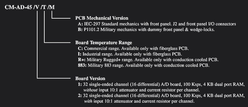
Ordering Example: CM-AD-45 /V /T /M
V (Board Version)
1: 32 single-ended channel (16 differential) A/D board, 100 Ksps, 4 KB dual port RAM, without input 10:1 attenuator and current resistor per channel.
2: 32 single-ended channel (16 differential) A/D board, 100 Ksps, 4 KB dual port RAM, with input 10:1 attenuator and current resistor per channel.
T (Board Temperature Range)
C: Commercial. Fiberglass PCB only.
I: Industrial. Fiberglass PCB only.
R+: Military Rugged+. Conduction cooled PCB only.
883: Military 883. Conduction cooled PCB only.
M (PCB Mechanical Version)
A: IEC-297 Mechanics with front panel I/O connectors.
B: P1101.2 Military mechanics, dummy front panel & wedge-locks.
Ordering Example
Part Number Example: CM-AD-45/2/R+/B
- 32 single-ended channel A/D board, 100 ksps, 4KB dual port RAM, with input attenuator.
- Military Rugged+ range (-40 to +85°C operating).
- IEEE P1101.2 Military mechanics with wedge-locks.
Documentation
LEVEL 1, CM-AD-45 MAP: User´s manual. Module hardware functional description oriented toward software development.
LEVEL 2, CM-AD-45 MMT: Maintenance manual. Extended description intended for failure location in the module.
Software Support
Wind River Systems VxWorks Tornado: The CM-AD-45 is supported by VxWorks Tornado. This operating system is ideal for developing real time software under UNIX environments. A complete "C" language driver in source code is available at low cost. Drivers include a floppy-disk and user's manual.
Generic "C" Language Driver: A generic "C" language driver is also available in source code. The user may freely adapt for any application, operating system or ANSI "C" compiler. This code has been successfully compiled with the well established Mentor Graphics toolset.
* NOTE - Drivers for other leading operating systems can be optionally supplied under request.