CM-MIL-SFF Description
Small Form Factor, sealed military enclosure that is conduction-cooled and designed exclusively for applications where customers may wish to install custom, highly integrated electronics.

The enclosure is available with or without power supply to provide extra space for the installation of payload electronics that can be directly powered via the application platform. COM Express, PCIe or even single or dual 3U payload cards, etc. may be integrated.
For stand-alone systems, a total output power of up to 150 watts is available from an integrated PSU. Single and dual redundant PSU options are available, accepting primary and secondary AC/DC input voltages from 9-375VDC and 90-264VAC to support a wide variety of applications.
Internal layout is divided into 2 independent metallic partitions. Payload area and PSU section at the side. This improves EMI/EMC performance & reduces PSU noise on system electronics.
CM-MIL-SFF
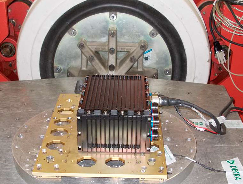
Heat generated within the enclosure is dissipated by a combination of conduction, radiation and free-air convection through the chassis metalwork & extended fins to the ambient environment.

The self-dissipation capacity of 50W @ 55ºC is not dependent upon cold plate mounting but is recommended to improve thermal performance and decrease payload Delta-T by approximately 12-15ºC, doubling the MTBF of the enclosed electronics.
Units fitted with an integrated PSU are given the option of a 'STANDARD' and 'PLUS' version. The PLUS version includes a Temperature Supervisory Unit, cold start up heaters, double capacitor bank for extended hold up time and remote control operation via front panel connector.
Front panel indicators are fitted as standard in the 'PLUS' version but are optional in the 'STANDARD' version for additional cost savings.
Enclosure Performance
Dissipation:★☆☆☆
Price:★★★★
Sealed:
Payload Dissipation:50 Watts @ 55ºC (no cold plate)
The small form factor enclosure is suitable for low wattage sealed applications that demand increased passive cooling capabilities (+30% dissipation with regard flat box alternatives).
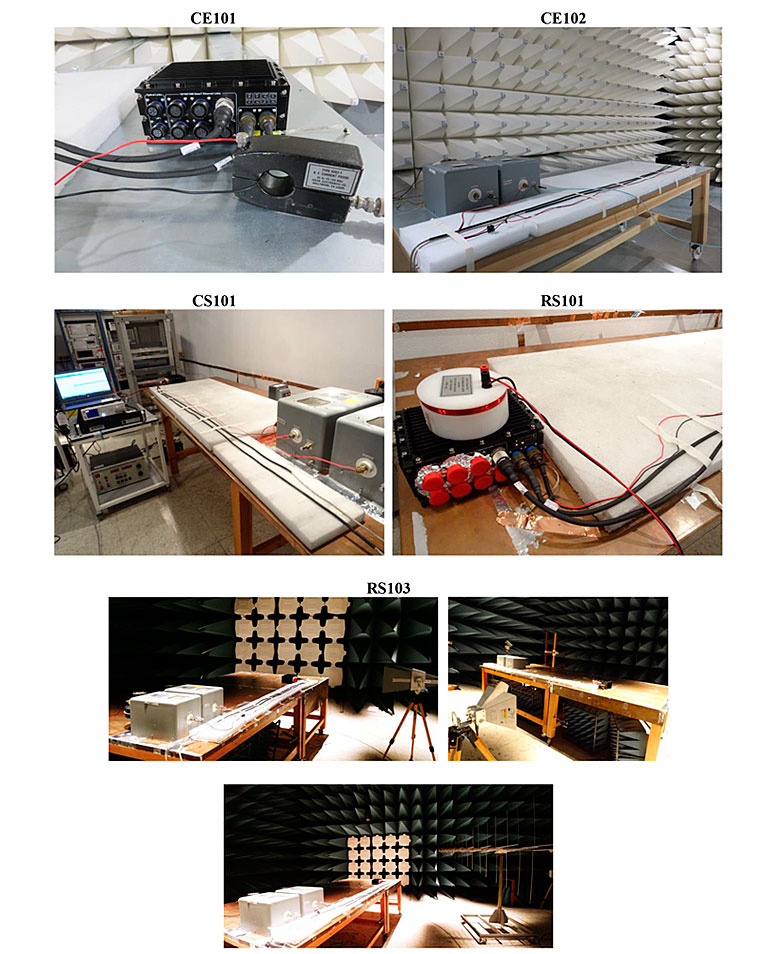
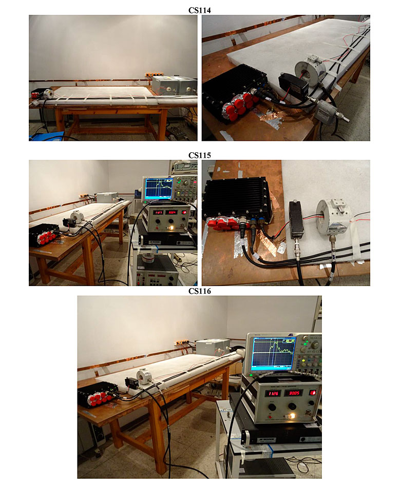
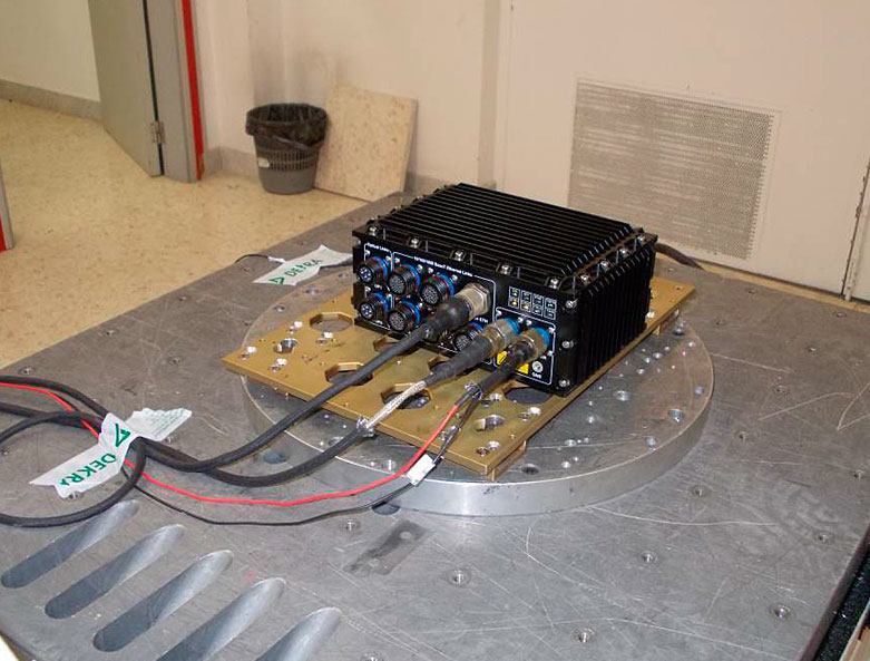
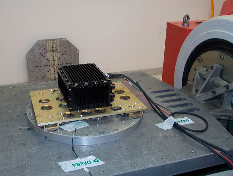
For reliable operation it is recommended the maximum Payload Power not be exceeded. Subject to operating conditions. All CM enclosures are delivered tested, qualified and certified per Military Standards MIL-STD-461E & MIL-STD-810F.
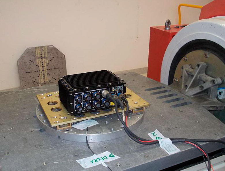
The enclosure can be easily mounted via base or side plate panel per-drilled threaded holes. Custom connector Front Panels, enclosure metalwork modifications and mounting options can be designed upon request, this may include for example, rear panel fixings, protruding bottom cover legs, front NAS-622 hooks and self-clinching pilot pins, or other.
The small form factor enclosure is ideal for multiple military applications that are of limited space, weight sensitive, in close proximity to an operator and in a deploy & forget scenario.
Payload Electronics
The versatility of the CM-MIL-SFF military enclosure offers a 'no limit' philosophy to end applications. Customers may choose to integrate any custom or Modular Open Systems Architecture (MOSA) to deliver a fully military rugged solution that may board any platform.

Small Form Factor (SFF) electronic modules may be integrated, stacked and enclosed to generate a multitude of products orientated for military or highly rugged programs.
Architectures such as COM Express, PCIe, MiniPCIe, SMARC, VNX, PMC, XMC, VPX or cPCI Serial system payload configurations can be realized and tailored for greater Size, Weight, Power and Cost (SWaP-C) in avionic and military sectors.
Single or dual 3U format VPX or cPCI-Seial modules may be accommodated, allowing customers to develop 'turn-key' solutions that pin-point specific opportunities faster, more confidently, and with greater flexibility.
System Management & Control
'PLUS' versions integrate a Temperature Supervisory Unit (TSU) with panel LED (over/under temperature) that controls Power Supply & Fan operation. Remote optoisolated control switches for ‘Battle-short’ & chassis PSU ‘on/standby’ are fitted as standard.

Systems fitted with the CM integrated Power Supply will benefit by having the ability to intercommunicate with the PSU, interrogate and receive the following information:
- Power Fail Monitoring.
- Reset Control / Shut Down / Standby Control.
- Thermal Monitoring.
- LED indicator signaling.
The user defined Front panel is delivered full machined and silk screened, ready to accept customer connectors. I/O wiring and integration of payload electronics is our customer's task. CM can provide this service on large order quantities upon request.
Case Study - Military Switch
Military Switch, CM-MIL2004-HSR, developed for military land vehicles and multiple platform applications. The enclosure is fitted with the latest generation Quad-core ARM CORTEX-A53 and dual core CORTEX-R5 real-time processors.

The 20 Port GbE + 4 port 1000-Base fiber optical link general purpose Switch is fully military compliant and qualified. This 'turn-key' system builds on PCB-FLEX-PCB technology
Front Panel connectors and signals lines union in a rigid PCB that links via Flex circuits to the conduction-cooled motherboard.
Signal integrity, wiring density and performance are all highly optimized in this COTS SwaP solution. The CM-MIL2004-HSR 'PLUS' version is delivered with a dual redundant PSU and all premium features of the supervisory system.
Read More
CM-MIL-SFF Power Supply
The CM-MIL-SFF PSUs supports a wide variety of AC/DC input voltages (MIL-STD-704 & MIL-STD-1275) and DC power output combinations up to 150 Watts. Available in 4 different versions (A-B-C-D) to suit the application DC Line requirements.
| 28VDC | OTHER | +5VDC | +3.3VDC | +12VDC | -12VDC | |
|---|---|---|---|---|---|---|
| A-50W | * | 40A | 22A | 8A | 8A | |
| B-50W | * | 40A | 22A | 12A | 12A | |
| C-75W | * | 40A | 22A | 8A | 8A | |
| D-150W | * | 40A | 22A | 12A | 12A |
The SFF power supply unit is extremely versatile in order to cover the full range of system applications regardless of the available end platform primary (main) and secondary power voltage. The three integrated high performance PSU blocks incorporate a range of features that are only available in latest generation advanced military systems.
When reliability is mission critical and faults are not tolerated, the ‘PLUS’ dual redundant PSU version ensures low stress load sharing for the twin DC/DC converters and mitigates the risk of an output power failure. A wide variety of single or redundant AC/DC power input combinations are supported as standard to guarantee flawless operation in worst case scenarios.
TSU Power Supply Specifications
- PSU operating Temperature: -40 to +90ºC.
- PSU storage Temperature: -50 to +120ºC.
- PSU DC/DC converter average efficiency: 89%.
- PSU Hold-up Time: 56 ms @ 28VDC - 40W.
- DC/DC converter in-to-out galvanic isolation: 3000 Vrms .
- DC/DC converter baseplate-to-out galvanic isolation: 500 Vrms.
- DC PSU over-voltage transient suppression: 2.5x nom. 12.5 ms.
- AC PSU over-voltage output surge suppression: 1Kv during 50 μs.
- PSU DC power output Ripple and Noise: less than 30 mV RMS.
Power Supply Features
Oversized In-line - EMI/EMC Filters Low and High frequency filters are fitted for full MIL-STD-461G compliance. These filters have been selected-on-test (matched) in Official Labs for performance.
PSU Input Protection - The Switch dual PSU modules are reverse polarity protected, also fitting an inrush current and over voltage limiter.
DC/DC Converters - Installed DC/DC converters provide over current and short circuit protection, input/output galvanic isolation, thermal protection and military temperature range.
Extended Hold-up - An oversized set of hold-up capacitors are fitted to maintain Switch circuitry DC voltages in the event of momentary power loss of the PSU input voltage.
Time Delay Fuses - Six military PCB fuses are fitted across the dual PSU modules in order to provide protection to the front end stage, DC/DC converters and TSU power electronics.
Power Fail Monitor - A power supervisory device continuously monitors the primary AC or DC Switch PSU input power voltage and notifies the payload when power failure is imminent.
DC Supervisor - The PSU DC output voltage is monitored via a micropower chip to ensure voltage level is within a specified tolerance. The monitor chip illuminates the panel ON green LED when payload voltage is in range.
PSU Faraday Cavity - The internal Switch layout incorporates an independent metallic partition for housing the PSU modules and in-line filters. This greatly reduces PSU heat and avoids electrical noise on payload electronics.
Dual Input Diode - A dual diode with common cathode is installed on the rear of the front panel when the STD Switch is ordered for redundant operation with two external batteries.
Input Power Configurations
1. DC INPUT SINGLE PSU (1SDC): Suited for UAVs, light armored vehicles and mobile ground weapon or communication systems equipped with DC batteries.
2. AC INPUT SINGLE PSU (1SAC): Ideal for Navy and Aircraft platforms fitted with 115 or 220VAC generators. This configuration is also suitable for laboratory and maintenance facilities.
3. REDUNDANCY VIA TWO DC BATTERIES WITH COMMON GND SINGLE PSU (2SDC): Ideal for military UAVs, mobile ground weapon systems and heavy armored vehicles fitting multiple DC battery banks that share a common ground.
4. INDEPENDENT AC INPUTS DUAL REDUNDANT PSU (2DRAC): Suited for mission critical AC applications aboard Navy and Aircraft platforms that require dual redundancy, greater reliability and extended MTBF.
5. INDEPENDENT AC + DC INPUT DUAL REDUNDANT PSU (2DRACDC): Ideal for multi-role mission critical applications that require both AC and DC dual redundancy, greater reliability and extended MTBF.
6. INDEPENDENT DC INPUTS DUAL REDUNDANT PSU (2DRDC): For mission critical UAVs, ground systems and heavy armored vehicles that require full dual DC redundancy, greater reliability and extended MTBF.
7. SINGLE DC BATTERY INPUT DUAL REDUNDANT PSU (1DRDC): For single battery mission critical UAVs, mobile weapon systems & light armored vehicles requiring dual redundancy, greater reliability & extended MTBF.
8. SINGLE AC INPUT DUAL REDUNDANT PSU (1DRAC): For single AC generator mission critical UAVs, Navy and Aircraft platforms requiring dual redundancy, greater reliability and extended MTBF.
Supervisory System
A Temperature Supervisory Unit (TSU) is fitted in the ‘PLUS’ version. This device protects electronics against extreme climatic conditions, switching the power supplies OFF (Standby) when the internal temperature is under or over the established limits. Users may set HI & LO temperature trip-points to regulate and optimize the system safety operational temperature range.

| BATTLE Remote | STANDBY Remote | SYSTEM POWER SUPPLY & TSU STATUS |
|---|---|---|
| Switch-OFF | Switch-OFF | NORMAL OPERATION. Both PSU and TSU operate normally. |
| Switch-OFF | Switch-ON | PSU in STAND-BY MODE. The PSU converters are forced to stand-by. No DC power is available to the digital payload. The TSU operates normally. |
| Switch-ON | Switch-OFF | BATTLE MODE (TSU DISABLED). The PSU is operating normally. The TSU is not allowed to shut-down the system power regardless of temperature. |
| Switch-ON | Switch-ON | PSU in STAND-BY MODE. The PSU converters are forced to stand-by. No DC power is available to the digital payload. The TSU is disabled. |
Heating elements are also fitted for mitigating against cold startups. An ‘early warning’ signal advises the digital electronics prior to shutdown-to-standby, allowing critical data to be orderly stored and saved. Power is restored once internal temperatures are within operational limits. All functions can be user enabled or disabled by soldered bridges.
TSU Power Supply Specifications
- Provides +5VTSU DC output voltage, up to 2 Watts.
- Autorange input 80-265 VAC 20-1000 Hz. 7 mA typical.
- 28VDC 32mA, 48VDC 18mA, 270VDC 4mA typical (±40%).
- Output current short circuit protection in +5V_TSU: 400 mA.
TSU Heater Elements
- DC 12 VDC @ 3.3 Amps. - DC 270 VDC @ 0.15 Amps.
- DC 28 VDC @ 1.5 Amps. - AC 115 VAC @ 0.3 Amps.
- DC 48 VDC @ 0.8 Amps. - AC 220 VAC @ 0.18 Amps.
The user defined Front panel is delivered full machined and silk screened, ready to accept customer connectors. I/O wiring and integration of payload electronics is our customer's task. CM can provide this service on large order quantities upon request.
System Management & Control
Systems fitted with the CM integrated Power Supply will benefit by having the ability to intercommunicate with the PSU, interrogate and receive the following information:
- Power Fail Monitoring.
- Reset Control / Shut Down / Standby Control.
- Thermal Monitoring.
- LED indicator signaling.
Thermal Monitoring - The Low and High TSU temperature trip points are user adjustable through two multi-turn trimming resistors located in the power supply PCB. Factory presets fitted with fixed resistors can be installed in production series.
Thermal Heaters - Resistive heating elements powered by the TSU are bolted to the enclosure frame in order raise internal temperatures during cold startups.
Battle Short Switch - Ability to disable the TSU during emergency or battle situations via a remote ‘Battle short’ switch. This bypasses/overrides all critical TSU functionalities despite the risk of payload temperature over-stress.
Reset Push Button - A remote push button allows to reset the Switch digital payload without switching off the mains breaker. TSU remote operations can be manually activated by an operator or via a master computer.
Delayed Shut-down - An AC/DC FAIL* signal advises the Switch CPU when power failure is imminent prior to power shut-down. Ethernet communications and critical data in memory, etc may be orderly stopped or saved.
PSU Standby Switch - Allows the user to manually set the system to ‘low power’ Standby mode without requiring to switch off the mains breaker, should the system be required to operate for a few hours but remain available on demand.
Power Supply - TSU circuitry is powered by an independent +5VTSU @ 2 Watt PSU. This module is permanently connected to the Switch primary power input & remains operational during Standby.
Front Panel LEDs - TSU status & operations can be visualized in real time via three chassis front panel LEDs: TSPW (TSU power on), TSHI (system over temperature) and TSLO (system under temperature).
Features

Removable Covers
The machined enclosure covers/panels are easily removable for maintenance and disassembly via stainless steel captive screws.
Mounting Holes
The enclosure can be easily side plate panel mounted or base mounted via six per-drilled threaded holes.
Cooling Fins
Fitted with over-size cooling fins on top cover and side panels to maximize radiation & natural convection cooling.Front Panel
Custom layout with client logo, connectors & silk-screening or a general purpose panel with MIL-C-38999 connectors is supplied.
LED Front Panel Indicators
Up to 8 front panel LED indicators for chassis monitoring; power on/off status, system board failure, input voltage, temp., etc.
Marking Plates
Bottom marking plate area for system specification data and rear panel marking area for serial number indication.
Sealed EMI Gaskets
All joints incorporate particle-filled silicon rubber DTL-83528C EMI beading for superior shielding, environmental sealing & thermal transfer.
Cold Start-up Heater
Resistive heating elements are installed in the 'PLUS version' and controlled by the supervisory system to minimize the effects of cold startups.
Inline Input Filter
A high capacity integrated EMI/EMC input voltage filter and PSU module discrete parts are fitted as standard to comply with MIL-STD-461F.
Hold-up Capacitors
PSU incorporates oversized hold-up capacitors intended to maintain DC voltages to payload electronics in the event of momentary power loss.
DC/DC Converters
Isolated VICOR DC/DC converters installed for single/dual redundant configurations. AC & DC VICOR modules incorporate FIAM & FARM filters.
Military Paint & Coating
Painted with a 3-layer military grade epoxy paint & primer. Machined aluminum anti-corrosion treatment MIL-STL-8170, Chromium(VI) Free.Capabilities
- Sealed, Contaminant-free enclosure
- Passive conduction-cooled with no fans
- Maintenance free operation
- Silent, no noise per Grade A12
- Low weight, optimized footprint
- Fully MIL-STD certified
- Up to 50W* Total Payload Power (30ºC Delta-T)
- Up to 150Wª dual redundant PSU configuration
- For Small form factor electronics (COMe, PCIe, MiniPCIe, etc)
- Removable Covers and Panels
- In-line EMI/EMC MIL-STD-461F Filter
- Integrated Temperature Supervisory Unit (TSU)ª
- Front panel user indicators
- Flexible I/O wiring
- Military Operating Temperature (-40°C | +85°C)
- Customizable to specific requirements
ª In PLUS versions only
Specifications
CM-MIL-SFF (With PSU) |
CM-MIL-SFF (No PSU) |
|
| WIDTH | 232 mm | 232 mm |
| HEIGHT | 103 mm | 103 mm |
| DEPTH | 155 mm | 155 mm |
| PAYLOAD AREA | 155 mm x 80 mm x 135 mm | 215 mm x 80 mm x 135 mm |
| WEIGHT | 2.8 Kg | 1.9 Kg |
| CPTR COEFF | ΔT/W = 1.43°C | --- |
| MAX PSU PWR | 150 Watts (D-150W) | --- |
| PSU V-INPUT | 28 VDC ±30%, 48 VDC ±30%, 72 VDC ±30%, 270 VDC ±30%, Autorange 90-132 VAC RMS & 180-264 VAC RMS 47-880 Hz, 3-Phase 200 VAC ±30% 47-880 Hz | --- |
| FRONT PANEL AREA | 125 mm x 140 mm | 125 mm x 140 mm |
| OPERATING TEMP | -40°C to +85°C Operating Temperature, -55°C to 100°C Storage Temperature | --- |
| MOUNTING OPTION | Baseplate or Side mounting | Baseplate or Side mounting |
COTS MODELS
This highly optimized small form factor enclosures incorporate all proprietary technologies, features and well established mechanical & electrical solutions developed during the past 30 years.
MIL Certificates


Ordering Information
CM-MIL-SFF /V /PI /SI /OP /FP /M /C
/V Version- 1: Standard Version - Single PSU with no Temp. Supervisor.
- 2: Plus Version - Dual redundant PSU with Temp. Supervisor.
- 115VAC: 115 VAC Input @ 40-880Hz.
- 220VAC: 220 VAC Input @ 40-880Hz.
- 12VDC: 12 VDC Input (9-36 VDC @ 50W).
- 28VDC: 28 VDC Input (9-36 VDC @ 50W or 18-36 VDC @ 75W).
- 48VDC: 48 VDC Input (36-75 VDC @ 75W).
- 270VDC: 270 VDC Input (180-375 VDC @ 75W).
- 115VAC: 115 VAC Input @ 40-880Hz.
- 220VAC: 220 VAC Input @ 40-880Hz.
- 12VDC: 12 VDC Input (9-36 VDC @ 50W).
- 28VDC: 28 VDC Input (9-36 VDC @ 50W or 18-36 VDC @ 75W).
- 48VDC: 48 VDC Input (36-75 VDC @ 75W).
- 270VDC: 270 VDC Input (180-375 VDC @ 75W).
- A-50W: 50W Output from single 9-36VDC PSU version.
- B-75W: 75W Output from single AC or 18-36VDC PSU version.
- C-100W: 100W Output from dual redundant 9-36 VDC PSU version (50W + 50W).
- D-150W: 150W Output from dual redundant AC or 18-36 VDC PSU version (75W + 75W).
- CMP: Standard CM front panel fitted with MIL-C-38999 connectors.
- UDP: User defined front panel layout (requires customer drawing).
- B: Base mounting via 6 M4 per-threaded holes in the baseplate.
- S: Side mounting via M4 per-threaded holes a the side-plate.
- B: Black, G: Navy Grey, E: Army Dark Earth, W: White, R: Red, PT: Platinum, YW: Yellow, GN: Green, BLU: Dark Blue, CR: Chromate MIL-C-5541 or O: Other (user defined).
CM-MIL-SFF/2/28VDC/220VAC/D-150W/UDP/B/E
- CM Small Form factor Enclosure.
- Sealed, passive cooled with heat dissipation fins.
- PLUS Version with Dual Redundant PSU & Temperature Supervisory System.
- 28VDC Primary Input power supply.
- 220VAC Secondary Input power supply.
- D-150W Dual Redundant Power Supply (75W + 75W).
DC line output: +5VDC @ 40A, 3.3VDC @ 22A, +12VDC @ 12A, -12VDC @ 12A. - User defined front panel layout (requires customer drawing).
- Base mounting points via 6 M4 per-threaded holes in the baseplate.
- Enclosure color is army dark earth.